


Making a person interface that visualizes a real-world construction — just like the Thirty Meter Telescope’s mirror — may appear to be a activity that calls for deep data of geometry, D3.js, and SVG graphics. However with a Giant Language Mannequin (LLM) like Claude or ChatGPT, you needn’t know all the pieces upfront.
This text paperwork a journey in constructing a posh, interactive UI with no prior expertise in D3.js or UI growth typically.
The work was finished as a part of constructing a prototype for an operational person interface for the telescope’s main mirror, designed to point out real-time standing of mirror segments.
It highlights how LLMs aid you “get on with it”, supplying you with a working prototype
even while you’re unfamiliar with the underlying tech.
Extra importantly, it reveals how iterative prompting — refining your requests step-by-step —
leads not solely to the fitting code but additionally to a clearer understanding
of what you are attempting to construct.
The Aim
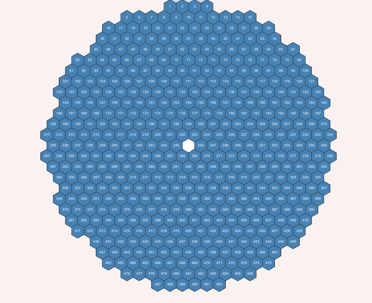
We wished to create an HTML-based visualization of the Thirty Meter Telescope’s main mirror, composed of 492 hexagonal segments organized symmetrically in a round sample.
We started with a high-level immediate that described the construction, however quickly realized that to succeed in my aim, I would have to information the AI step-by-step.
Step 1: The Preliminary Immediate
“I wish to create an HTML view of the Thirty Meter Telescope’s honeycomb mirror.
Attempt to generate an HTML and CSS based mostly UI for this mirror, which consists of 492 hexagonal segments organized in a round sample.
Total construction is of a honeycomb. The construction needs to be symmetric.
For instance the variety of hexagons within the first row needs to be identical within the final row.
The variety of hexagons within the second row needs to be identical because the one within the second final row, and so on.”
Claude gave it a shot — however the outcome wasn’t what I had in thoughts. The structure was blocky and never fairly symmetric. That is once I determined to take a step-by-step strategy.

Step 2: Drawing One Hexagon
“This isn’t what I would like… Let’s do it step-by-step.”
“Let’s draw one hexagon with flat edge vertical. The hexagon ought to have all sides of identical size.”
“Let’s use d3.js and draw svg.”
“Let’s draw just one hexagon with d3.”
Claude generated clear D3 code to attract a single hexagon with the proper orientation and geometry. It labored — and gave me confidence within the constructing blocks.
Lesson: Begin small. Affirm the inspiration works earlier than scaling complexity.

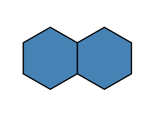
Step 3: Including a Second Hexagon
“Good… Now let’s add another hexagon subsequent to this one. It ought to share vertical edge with the primary hexagon.”
Claude adjusted the coordinates, putting the second hexagon adjoining to the primary by aligning their vertical edges. The structure logic was starting to emerge.
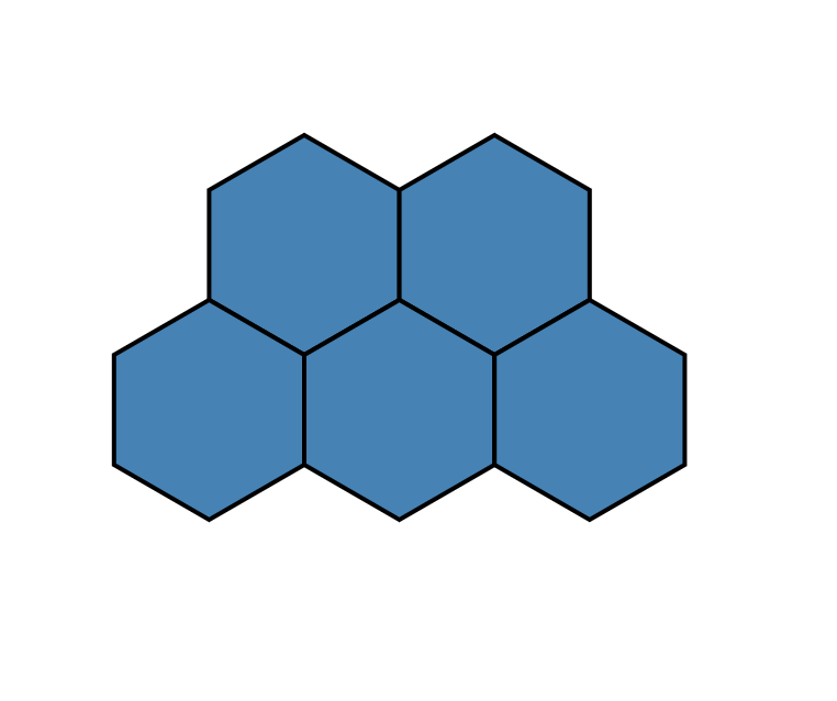
Step 4: Creating the Second Row
“Now let’s add another row.
The hexagons within the second row share vertical edges with one another much like the primary row.
The highest slanting edges of the hexagons within the second row needs to be shared with the underside slanting edges of the hexagons within the first row.
The variety of hexagons within the second row needs to be such that the primary row seems centrally positioned with the second row.”
Preliminary makes an attempt didn’t correctly align the slanting edges.
“Oops… this doesn’t share the slanting edges with the earlier row.”
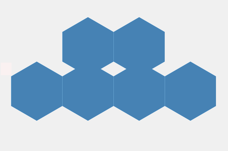
However ultimately, after clarifying spacing and offset logic, Claude acquired it proper.
Lesson: Geometry-based layouts typically require a number of iterations with cautious visible inspection.
Step 5: Increasing right into a Symmetric Construction
“Now we have to create greater construction with extra hexagons organized in additional rows such that:
The general construction seems round like honeycomb.
The variety of hexagons within the rows goes on growing after which goes on lowering to type a wonderfully symmetric construction.
The whole variety of hexagons must be 492 to match the TMT telescope.
We are able to have an empty hexagon (displaying empty house) precisely on the middle of the circle.”
Claude used a ring-based structure strategy to simulate round symmetry. However at first:
“This isn’t round however seems extra like a hexagonal general view…”
Then I instructed:
“Attempt with solely 6 hexagons within the first and final row.”
This modification improved symmetry and helped obtain a visually round structure. The variety of hexagons per row elevated after which decreased — precisely as desired.
Step 6: Tuning the Central Opening
“That is higher however we’d like a smaller opening on the middle.The black house on the middle is simply too huge. It needs to be at most 1 or a number of hexagons.”
By lowering the empty house and rebalancing the inside rings, we lastly acquired a well-packed, round construction with a small central hole — matching the TMT design.
Lesson: Use domain-specific constraints (like whole rely = 492) as guideposts for structure parameters.
Step 7: Including Numbering and Tooltips
“We wish to have a quantity on every hexagonal phase. They need to be numbered sequentially. The primary within the first row needs to be 1 and the final within the final row needs to be 492. After we present the hexagonal phase data on mouseover, we must always present the quantity as properly.”
Claude initially assigned numbers based mostly on ring index, not row order.
“You might be producing numbers based mostly on place within the ring… However the numbering needs to be row-based. So we must always one way or the other map the rings to the row. For instance, Ring 13 phase quantity 483 is in row 1 and needs to be numbered 1, and so on. Are you able to recommend a method to map segments from rings to rows this manner?”
As soon as this mapping was applied, all the pieces fell into place:
- A round structure of 492 numbered segments
- A small central hole
- Tooltips displaying phase metadata
- Visible symmetry from outer to inside rings
Reflections
This expertise taught me a number of key classes:
- LLMs aid you get on with it: Even with zero data of D3.js or SVG geometry, I may begin constructing instantly. The AI scaffolded the coding, and I realized by way of the method.
- Prompting is iterative: My first immediate wasn’t mistaken — it simply wasn’t particular sufficient. By reviewing the output at every step, clarified what I actually wished and refined my asks accordingly.
- LLMs unlock studying by way of constructing: In the long run, I did not simply get a working UI. I acquired an comprehensible codebase and a hands-on entry level into a brand new expertise. Constructing first and studying from it.
Conclusion
What began as a imprecise design concept changed into a functioning, symmetric, interactive visualization of the Thirty Meter Telescope’s mirror — constructed collaboratively with an LLM.
This expertise reaffirmed that prompt-driven growth is not nearly producing code — it is about pondering by way of design, clarifying intent, and constructing your means into understanding.
When you’ve ever wished to discover a brand new expertise, construct a UI, or deal with a domain-specific visualization — do not wait to be taught all of it first.
Begin constructing with an LLM. You may be taught alongside the way in which.


